Atari rheostat volume knobs!

Once in a while, something so simple comes along that it just deserves to be discussed and shared. Then you start to wonder, “how did I get along without that for so long?”

During my last Bob Roberts order, I was perusing the website to make sure I had everything I needed. I knew that Bob sold volume/pot knobs — and quite a variety at that — but this time I noticed that a few were specifically aimed at the infamous finger-crushing Atari rheostat.

no images were found

Let’s back up for a second…what the heck is a rheostat??

Many typical potentiometers are designed for 250 or maybe 500mW. A rheostat, on the other hand, is engineered to dissipate much more power, and are therefore typically rated for several Watts.

In games where the volume adjust is working on a low-level audio signal, a regular potentiometer will suffice just fine. However, on some games, because Atari wired their volume adjusts after the amplifier, something that can handle more power needed to be used. Some of the games that used them are Lunar Lander, Asteroids Deluxe, Battlezone, Firefox, Major Havoc, Missile Command, Pole Position, Red Baron, Space Duel, Tempest & Warlords.

Ok…so, why did Atari use them? Well, in simple terms, it was most likely just an engineering decision. Atari’s gameboards of the time output the volume at full blast. The rheostat was connected directly to the speaker lines. Thus, a wirewound rheostat had to be used because of it’s wattage handling capabilities.

In this case, an Ohmite 50 Ohm, 12.5 Watt rheostat was used, Atari part #RES50R.

So, anyone with one of these older games knows that these old Ohmite rheostats are painfully difficult to turn, mostly because of their mechanical structure – a thick wiper element that runs along a large, heavy wirewound base. I’ve heard it described before as “trying to turn a slippery toothpick.”

So…back to the knobs on Bob Roberts’ website. I got the $2 version, and let me tell you…this is the best $2 I’ve spent in a long while. My Pole Position II, Tempest and Missile Command all got one, and my fingers have never been happier…

Like us on Facebook!

facebook.com/stardustarcade

Tempest repair log – auto firing logic issue

Status: FIXED

Repair cost:  $0.50

KLOV Posthttp://forums.arcade-museum.com/showthread.php?t=156908

Symptom:  Single shot firing doesn’t work.  Holding fire button down for auto-fire does work.

Diagnosis:  Since firing works, button is working.  Logic issue.

Fix:

  • 10/30/2010 – Traced fire button back to 74LS157 @ D6 (Aux board).  Replaced chip and single shot firing now works.

Tempest repair log – AVG (main) board issue

Status: FIXED

Repair cost: $2 (questionable if part was really needed)

KLOV Posthttp://forums.arcade-museum.com/showthread.php?t=146427

Symptom:  Game board exhibiting strange display behavior – random vectors scrolling back and forth across screen.  Game plays blind.

Diagnosis:  Problem located on AVG board.

Fix:

  • 08/21/2010 – AUX board and cable verified good.  Tested individual boards on a working setup.  Problem is located on AVG board.
  • 08/22/2010 – Cleaned and reseated 5 socketed RAMs, the 2 vector ROMs, and the CPU.  Board now has no XY output voltage.
  • 08/24/2010 – Tested several chips in the vector generator data shifter section, which confirmed good.  Logic probe pointed to DAC-312 @ D10.  Replaced with no change.
  • 10/30/2010 – Began with game in test mode, no display.  Swapped CPU with known working 6502 and got a single blue vector on screen and activity on the slam switch (switches test screens) and long steady beep.  Confirmed activity on CPU pin 37 & 39.  Activity on E2 pin 1 & 2.  Confirmed ROM activity on the CS1 & CS2 lines.  Theory of operation doc said long steady beep in test mode points to bad vector ROMs.  Flip-flopped the ROMs (socketed) and test pattern appeared.  Adjusting X/Y position, linearity and BIP controls brought test pattern into view.  Went out of test mode and game worked.

Notes: DAC replacement could have had an effect, but hard to tell since game was dead – DAC outputs never changed, but inputs upstream were still bad at that point.   However, after the DAC replacement, I never saw the pattern shown in the video again. Original CPU was later confirmed good.  Bad/dirty sockets ended up being the culprit despite cleaning of chip legs and using contact cleaner before they were inserted into their respective sockets.

Sanyo EZV-20 monitor repair log – HV shutdown

Status: FIXED

Repair cost: About $18

KLOV Post: http://forums.arcade-museum.com/showthread.php?p=1355615

Symptom:  Post-cap kit, monitor in HV shutdown, shakes, vertical collapse

Diagnosis: Voltage regulator bad?  Also could be B+ pot.

Fix:

  • 7/23/2010 – After a cap kit, monitor went into HV shutdown shortly after being powered on.  B+ at 137v.
  • 9/24/2010 – Replaced Q901, IC601, VR601 (B+ pot).  Monitor now has the shakes (video). B+ sitting at 110-111v.
  • 2/6/2012 – Replaced TR402/TR403, monitor now has vertical collapse.
  • 2/12/2012 – VR354 is stuck at 18kOhm, and adjusting it does nothing, thinking pots might be bad?  Removed it, and once out, it tested good.
  • 3/3/2012 – Tested R473 (1 ohm, by the flyback) and it was bad. Replaced it with a 1/2 watt. R477 tested fine, but flaky, and looked pretty bad/burnt…easy decision to replace it.  3.3ohm metal film fusible, 1 watt.

I later learned that sometimes the following resistors should be changed out during a cap kit on the Sanyo 20EZV. The majority of cap kits out on the market do not include them. They are included in the Zanen kit and the Twisted Quarter kit. Failure of any one of these 3 resistors can cause vertical collapse after completing a cap kit on a Sanyo 20EZV.

R472 – 33 ohm 1/4w
R473 – 1 ohm 1/4w
R478 – 1 ohm 1/4w

Big thanks to Dave Okert and his Sanyo 20EZV Flow Chart, which is a great starting point for any Sanyo repairs!

Links:
Sanyo 20EZV Flow Chart
Sanyo 20EZ Troubleshooting Guide

Tempest monitor repair log – WG 6100 color vector monitor rebuild

Status: FIXED

Repair cost: About $50

KLOV Posthttp://forums.arcade-museum.com/showthread.php?t=98417

Symptom:  Monitor dead.  Original 6100, fireworks on deflection board, R100 burned through.

Diagnosis: Low voltage section of deflection board is toast.  Perform cap kit, install LV2000, concentrate on chassis transistors & power transistors on deflection board.

Fix:

  • 08/02/2009 – Installed cap kit + extra parts, LV2000.  F100 & F101 blow immediately after powerup.
  • 08/18/2009 – Replace diodes, transistors on LV2000.  Replace blown (underrated) D100-103 with 6A2 diodes.  Replace Q603/Q703 on frame.
  • 08/24/2009 – Learn, inspect work, double-check, triple check…smoke test tonight.  Deflection board fixed – we have monitor chatter, but only half a picture.
  • 09/17/2009 – F600 now blowing on powerup.  Replaced blown Q606.  Powers up and runs for about 5-6 seconds with vertical line before F600 blows again.
  • 06/25/2010 – Replaced all frame mounted transistor sockets with new ones.  Monitor now powering up.  Issue with Tempest boardset (link), monitor verified working with another color vector game.

Notes:

The frame-mounted transistor sockets were most likely causing intermittent/bad connections from the corroded and weakened leafs.  The intermittent connections were eventually leading to the transistors shorting out, causing a domino effect of other parts to fail, or a fuse to blow.  Every time a fuse would blow, the proper thing to do would have been to test all the transistors (on the frame and deflection board) for shorts before continuing.  Replacing all 6 sockets eliminated this issue.

Eventually, the culprit parts were the MPSU07/57 power transistors on the deflection board.  These parts are very expensive and/or hard to find, but I bit the bullet and replaced them all, which fixed the problem.

Pole Position 2 repair log – “hard right” steering issue

Status: FIXED

Repair cost: $0 (Used part from stock)

KLOV Posthttp://forums.arcade-museum.com/showthread.php?t=135387

Symptom:  Hard steering to the right sometimes registers as going in a straight line.

Diagnosis: Noticed encoder was smaller than encoder from a spare PP control panel I had.

Fix:

  • 05/26/2010 – Current encoder being used seems to be from a spinner assembly.  Replace encoder with correct one, and steering is working fine now.

Gorf repair log – Space Cadet level indicator issue

Status: FIXED

Repair cost:  42 cents

Symptom:  Space Cadet light doesn’t work.

Diagnosis:  Test bulb/sockets, check level section circuits.

Fix:

  • 12/2/09 – Swapped bulbs, sockets to test in other rank lights that were working (i.e. Space Captain).  Replaced all bad bulbs that were found, verified all sockets were working.  Light still not working.  Tested caps and transistors, found a bad ceramic cap and one bad transistor.  Replaced bad ceramic cap.  No change.
  • 12/3/09 – Replaced TIP-110 transistor, Space Cadet light now works.

Gorf repair log – Player 2 button stuck closed

Status: FIXED

Repair cost: 6 cents

KLOV Post: http://forums.arcade-museum.com/showthread.php?t=106860

Symptom:  2 coins always starts 2-player game.  Checked diagnostic screen and it showed P2 button always closed.

Diagnosis: Continuity between common ground (orange/red) and P2 button (red/yellow) lines all the way back to the board.  Problem on mainboard.

Fix:

  • 10/15/09 – P2 button: Pin 19 on J1 connector.   Runs thru R16, R32 which tested good.  Traced P2 line back to U3 (a MC14539B multiplexer IC) pin 10, which was stuck high.
  • 10/19/09 – With the help of a friend, realizing pin 10 on U3 is an input, something upstream must be causing the high signal.  Tested U3 for shorts (conductivity tests between inputs/Vcc), everything tested fine.  A series of pullup resistors and a cap is upstream of that pin….  Pulled resistors, which tested good.  Pulled C16 (104Z ceramic axial cap) which tested bad.  Waiting for parts.
  • 10/24/09 – Replaced C16, P2 no longer closed.

Satan’s Hollow repair log – 90412 power board causing resets/RAM errors

StatusFIXED

Repair cost:  About $7.

Symptom: Game resets during play, during movement, and sometimes shows “RAM Error B2” screen.

Diagnosis: 90412 power board had corrosion on J4, J5

Fix:

  • 9/27/09 – Replaced J4, J5 with new 15-pin AMP connectors.  Recapped board.
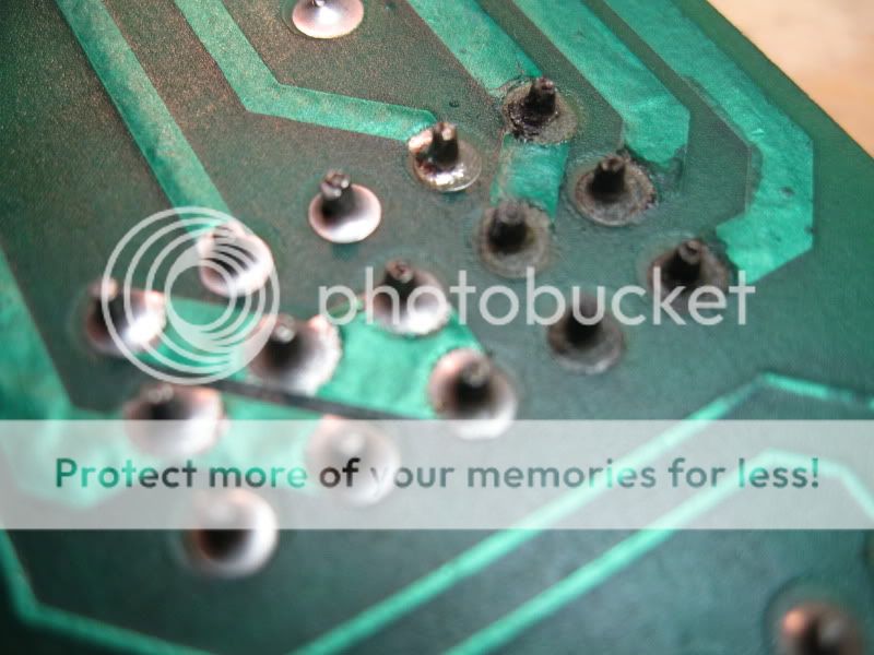
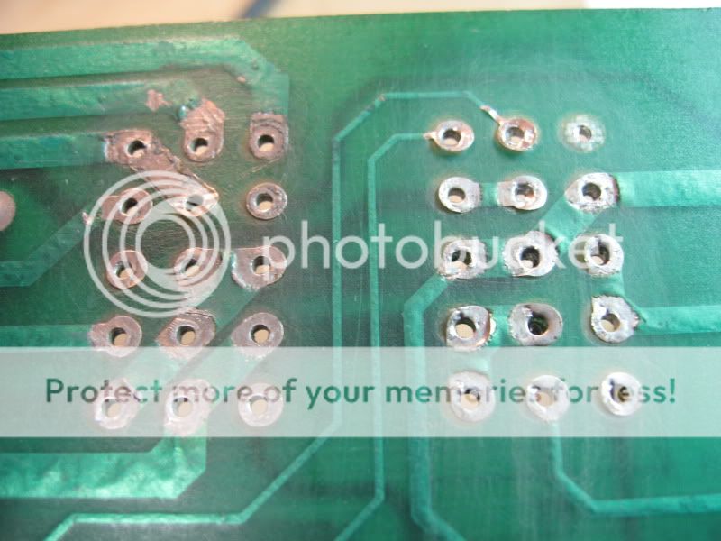
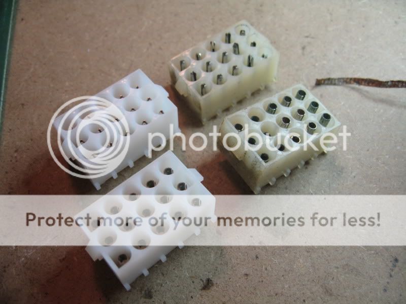
  • 9/28/09 – Tested board, adjusted +5v, +12v.  Tested adjusted voltages on J4/J5 pins based on schematic.